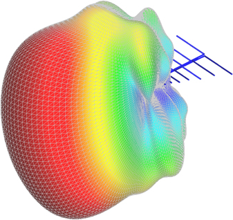
log periodic antenna radiation pattern
Use the lpda object to create a printed log-periodic dipole array antenna. Omni-directional radiation pattern 8.

Log Periodic Antennas Antenna Products
Calculate the radiation pattern and input impedance for a log periodic dipole array LPDA antenna.
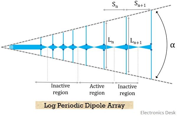
. A log-periodic antenna is used in a wide range of applications where variable bandwidth is required along with antenna gain and directivity. This antenna is widely used in communication and radar due to advantages such as wideband high gain and high directivity. In this article we will however focus mainly on the LPDA is its classic configuration along with several other offshoot derivatives.
In this paper the radiation pattern measurement of a log-periodic antenna is done on a new platform consists of GNU Radio Companion GRC and Universal Software Radio Peripheral USRP. CONCLUSIONS The design measurement and analysis of radiation patterns gain and VSWR of a 1690 MHz 2200 MHz log-periodic dipole antenna has been presented. Antenna bandwidth is defined concerning its design frequency often termed its center frequency.
This forms a simple way of performing the radiation pattern measurement at low cost compared to the conventional methods. Creation Syntax lpdipole lpda lpdipole lpda NameValue Description. For uni-directional Log-periodic antenna the radiation towards shorter element is of considerable amount whereas in forward direction it is small or zero.
This is the portion where maximum radiated energy exists. In that arrows signify radiation directions. If you need assistance beyond what is provided above please contact us.
The default antenna is centered at the origin and uses an FR4 substrate. It is a directional antenna so its radiation pattern is also uni-directional. Ad Order Our High Performance 380-6000 MHz DAS Antennas That Are Ideal For DAS Applications.
Non-radiating transmission lines are used to model the boom of the LPDA antenna. Here the radiation pattern has main lobe side lobes and back lobe. Comparison between simulations and measurements c.
The major part of the radiated field which covers a larger area is the main lobe or major lobe. ANTENNA DESIGN In LPDA all the dipoles are active elements the longest dipole works as reflector and successive dipoles act as directors. There are a variety of log-periodic structures and all of them are not frequency-independent.
The radiation patterns and gain at 200 500 700 and 1000 MHz are shown both as elevation and azimuth patterns in Figure 6. In the whole band the measured antenna gain exceeds the target value of 87 dBi and VSWR is below the desired limit of 15. THANK YOU FOR WATCHING BE SPARTAN.
The Fig1 shows the structure of log periodic dipole array antenna. The azimuth pattern is the field strength in the plane that the. In the antennas radiation pattern diagram the energy being radiated can be signified through the patterns illustrated in a specific way.
Log Periodic Dipole Array Antenna. This antenna is directive and shows end fire radiation pattern. The Radiation pattern of log-periodic antenna can be of uni-directional or bi-directional depending upon the log periodic structures.
Radiation patterns of a log-periodic antenna in the vhf band. This measurement is made in the direction of the highest antenna directivity. The LPDA is used extensively for HF VHF and UHF radio communications.
The direction of this lobe indicates the directivity of the antenna. Log Periodic Antenna Designing Equations for antenna Scale Factor sigma frac S_ n 2L_ n frac S_ n S_ n-1 σ 2LnSn Sn1Sn. The concept of the Log-Periodic array was initially conceived in the year 1958 by two researchers at the University of Illinois in the USA.
The elevation pattern is the field produced in a plane that slices through the boom of the antenna and is perpendicular to the antenna elements. Available For Same-Day Shipping. L-Com Keeps Networks Operating Anytime Anywhere.
If a 100-MHz center frequency log-periodic antenna is transmitted or received power is 3 dB down at 50 MHz and 200 MHz its bandwidth is 200 MHz 50 MHz or 150 MHz.

Figure 3 From Miniaturization Of Log Periodic Dipole Array Antenna Using Triangular Meander Structure Semantic Scholar
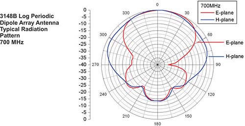
3148b Log Periodic Dipole Array Ets Lindgren

Measured Normalized Radiation Patterns Of A Euclidean And B Meander Download Scientific Diagram

Simulated And Measured Radiation Patterns Of The Log Periodic Antenna Download Scientific Diagram
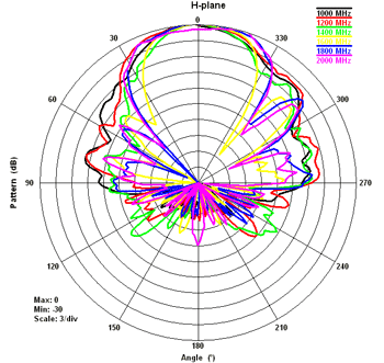
On The Radiation Patterns Of Common Emc Antennas

Design And Analysis Of Modified Log Periodic Dipole Antenna With Enhanced Gain Semantic Scholar

Pdf Design Of A Printed Log Periodic Dipole Array For Ultra Wideband Applications
Design Of Broadband Log Periodic Dipole Antenna Using Swarm Optimization
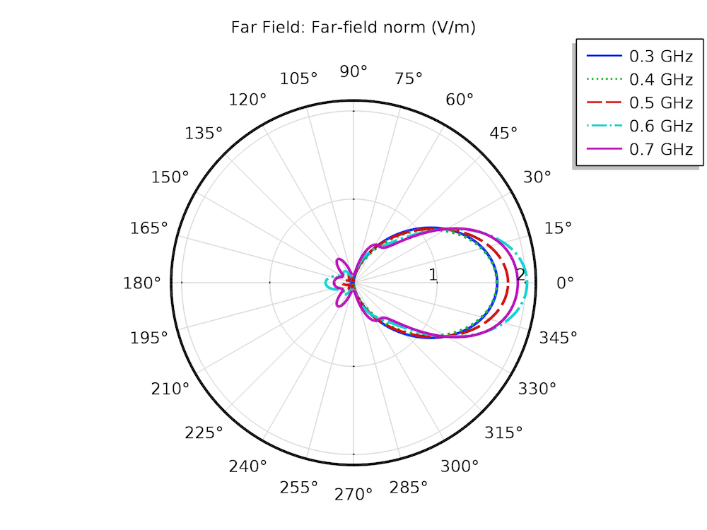
Designing Accurate Emc Emi Testing Equipment With Rf Modeling Comsol Blog

What Is Log Periodic Antenna Working Characteristics Advantages Disadvantages And Applications Of Log Periodic Antenna Electronics Desk

The Geometry And Radiation Patterns Of The 17 Element Log Periodic Download Scientific Diagram

Spacing Considerations Of Multiple Lpdas On A Mast Cojot

Simulated Radiation Patterns Of The Conformal Log Periodic Balloon Download Scientific Diagram
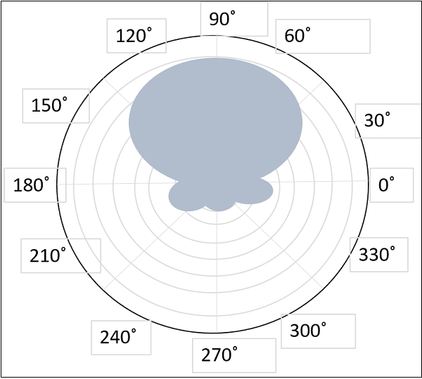
Antenna Theory Log Periodic Antenna
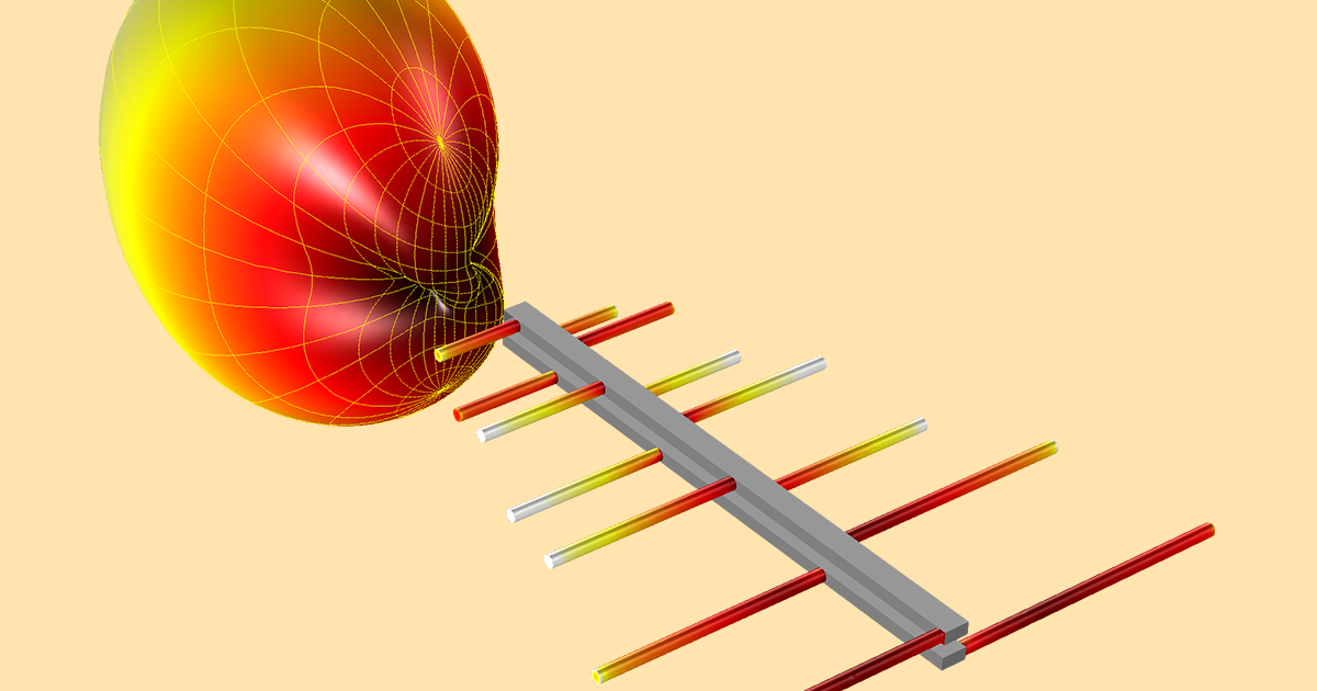
Designing Accurate Emc Emi Testing Equipment With Rf Modeling Comsol Blog
